


In this article, we take a detailed look at how each part of a hard disk drive works.
And if your hard drive ever fails with important files on it, Bot’s hard drive data recovery starts with a free diagnosis.
Don’t try this with your own drive: opening a hard drive outside a clean room can destroy it and the data on it!
If you’re curious about what’s inside, only take apart a drive that is already dead and holds no data you need (like the one we opened here).
A brief history of the hard disk drive
The hard disk drive has been the standard storage device in PCs around the world for more than 30 years, but the technology behind it is much older.
IBM launched the first commercial disk drive in 1956, with a capacity of 3.75 MB. Broadly speaking, its basic structure hasn’t changed much since then.
Drives still use magnetic disks to store data and heads to read and write it. What has changed, and dramatically, is the amount of data they can hold.
In 1987, a 20 MB drive cost around US$350. Today, the same money buys a 14 TB drive, with 700,000 times more space!
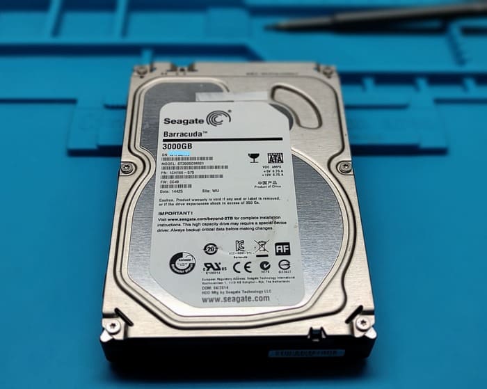
Hard disk drive composition
The drive we’ll be taking apart isn’t quite that big, but it’s still respectable: a 3 TB, 3.5″ Seagate Barracuda, model ST3000DM001, a drive known for its high failure rate.
The body of a hard drive is mostly cast metal. The forces acting on the drive under heavy use can be considerable, and thick metal keeps the chassis from flexing and vibrating.
Even tiny 1.8″ drives have a metal body, although it is usually aluminum rather than steel, since these drives are designed to be as light as possible.
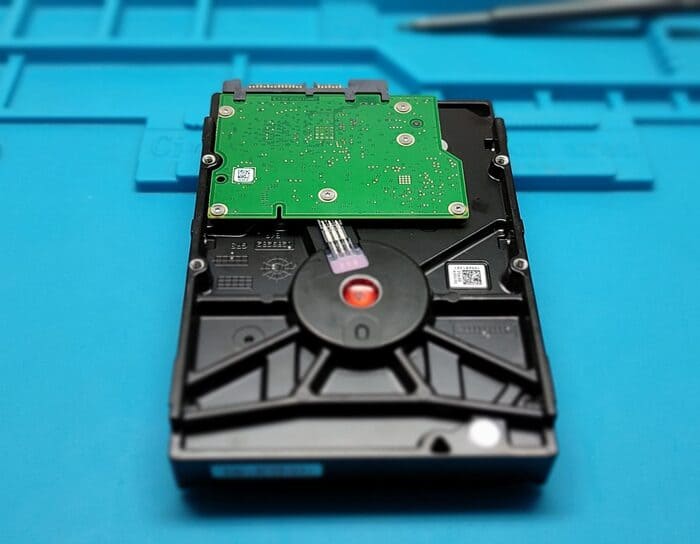
Connectors
Turning the drive over, we can see a circuit board and several connectors.
The connector at the top of the board is for the motor that spins the platters. The three at the bottom are, from left to right, the jumper pins used to configure certain drive settings, the SATA (Serial ATA) data connector and the SATA power connector.
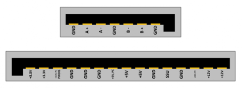
Serial ATA appeared in the early 2000s and is now the standard interface for connecting drives to the rest of a PC.
The specification has gone through many revisions since then, the most recent being version 3.5.
Our sample drive follows an older revision, but the only difference is a single pin on the power connector.
The data connector uses what is called differential signaling: the A+ and A- pins carry instructions and data from the computer to the drive, while the B+ and B- pins carry signals in the opposite direction.
Using paired wires like this greatly reduces the effect of electrical noise on the signal, which allows much higher speeds.
Power
On the power connector, there are several pins for each voltage (+3.3 V, +5 V and +12 V). Not all of them are actually needed, as hard drives don’t draw much power.
This Seagate model draws less than 10 W even under heavy load.
The pins marked P are precharge pins: they are longer, so they make contact first, which allows the drive to be connected and disconnected while the computer is running (hot swapping).
The pin marked PWDIS (Power Disable) lets the host cut power to the drive remotely to force a reset, but this feature only exists from SATA revision 3.3 onward; on our drive, it’s simply another +3.3 V line.
The last pin, marked SSU, simply tells the computer whether the drive supports staggered spin-up.
The platters inside the drive, which we’ll look at later, must reach full speed before the computer can use the drive.
In a machine with many drives, the sudden demand for power when they all spin up at once can destabilize the system.
Staggering the spin-ups prevents this problem, although it means waiting a few extra seconds.
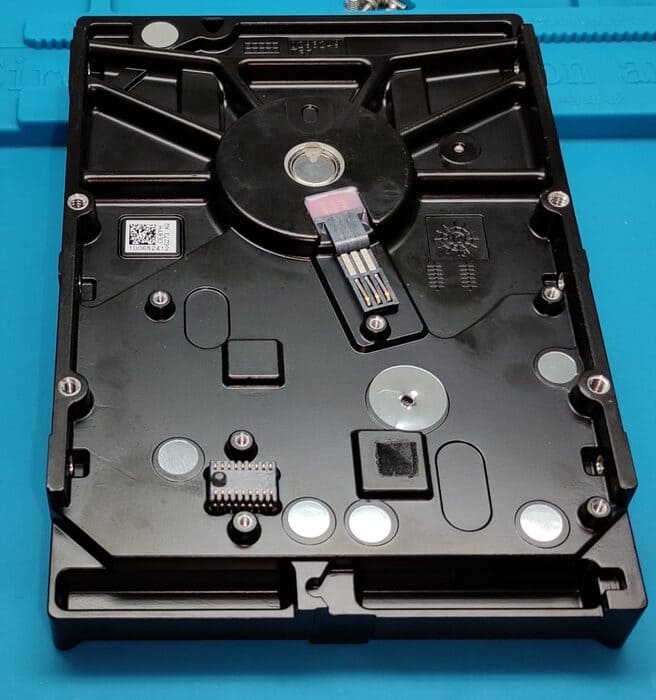
Logic board
Removing the circuit board shows how it connects to the components inside the drive.
Hard drives are not airtight, except for high-capacity models filled with helium instead of air. Helium is much less dense, which causes fewer problems in drives with many platters.
Even so, the inside of a drive can’t be left openly exposed to the environment.
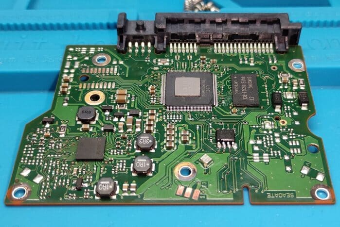
There is a small breather hole in the metal casing (the large white dot at the bottom left of the image above) that keeps the internal air pressure equal to the outside pressure.
With the circuit board removed, let’s see what’s on it. There are four main chips:
- LSI B64002: the main controller, which handles commands, the flow of data in and out, error correction and more;
- Samsung K4T51163QJ: 64 MB of DDR2 SDRAM running at 800 MHz, used as a data cache;
- Smooth MCKXL: controls the motor that spins the platters;
- Winbond 25Q40BWS05: 512 KB of serial flash memory that stores the drive’s firmware (a bit like a PC’s BIOS).
Across the wide range of hard drives on the market, the components on the circuit board differ very little.
Larger drives need more cache (the latest giants have up to 256 MB of DDR3), and the main controller may be a little more sophisticated in how it handles errors, but that’s about it.
Platters and spindle motor
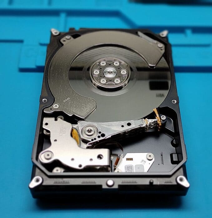
The large metal disk that takes up most of the drive immediately catches the eye, so it’s easy to see why these are called disk drives.
The platters are made of glass or aluminum and coated with several layers of different materials.
This 3 TB drive has three platters, so each one stores 1 TB, or 500 GB per side.
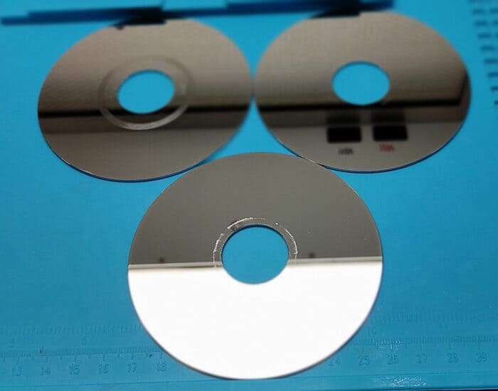
This photo of dusty platters doesn’t do justice to the engineering and manufacturing precision needed to make them.
In this drive, the aluminum platter is 0.04 inches (1 mm) thick, but it has been polished so finely that the average height of the surface irregularities is less than 0.000001 inches (about 25 nm).
On top of the metal sits a base coating just 0.0004 inches (10 microns) thick, made up of several layers of different compounds.
It is applied by electroplating followed by vapor deposition, which prepares the platter for the magnetic material that actually stores the digital data.
This material is usually a complex cobalt alloy, arranged in concentric tracks, each about 0.00001 inches (about 250 nm) wide and 0.000001 inches (25 nm) deep.
At the microscopic scale, the metal alloy forms grains, a bit like soap bubbles floating on water.
Each grain has its own magnetic field, which can be aligned in a given direction.
Groups of these fields represent the 0 and 1 bits of data.
The final coatings are a protective layer of carbon and then a polymer lubricant to reduce friction on contact. Together, they are no more than 0.0000005 inches (12 nm) thick.
We’ll soon see why the platters have to be made to such tight tolerances, but it’s amazing to think that for about $15 you can own a piece of nanometer-scale manufacturing!
Let’s go back to the whole drive and see what else is inside.
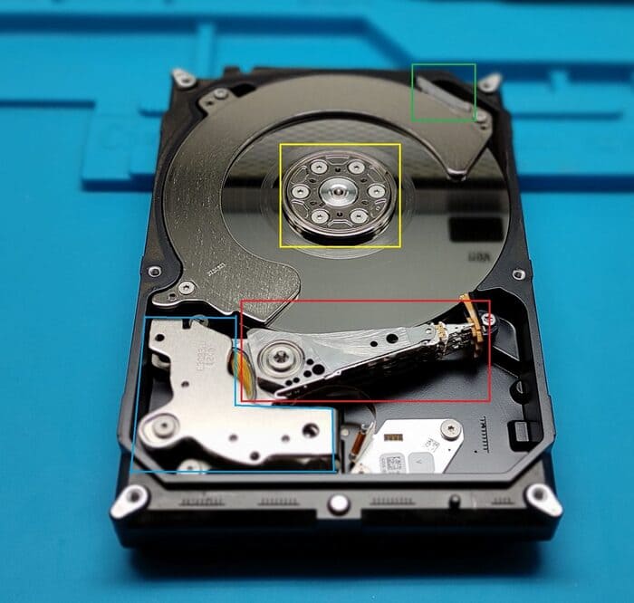
The part outlined in yellow is a metal clamp that holds the platters firmly on the spindle motor, the electric motor that spins them.
In this drive, the platters spin at 7,200 RPM, but other models spin more slowly.
Drives that spin more slowly are quieter and use less power, but they also perform worse, while the fastest drives can reach 15,000 RPM.
To limit the harmful effects of dust and moisture, a recirculation filter (green box) captures tiny particles and keeps them trapped.
The air moved by the spinning platters ensures a constant flow through the filter.
Above the platters, next to the filter, is one of the three platter separators: they help reduce vibration and keep the airflow as stable as possible.
In the top left corner of the photo, marked in blue, is one of the two permanent bar magnets.
They provide the magnetic field needed to move the component highlighted in red. Let’s remove some of these parts to get a better look.
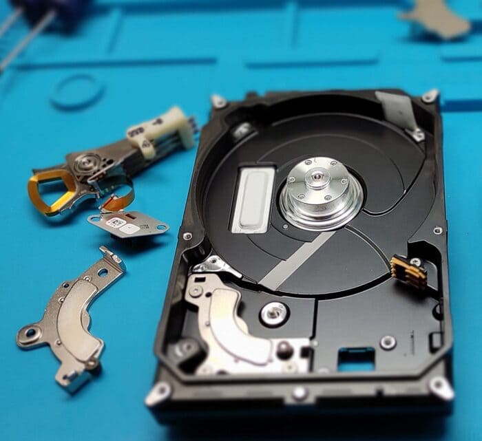
What looks like a thick adhesive bandage is another filter, the breather filter, which removes particles and gases from the outside air as it enters through the hole we saw earlier.
Inside the HDA
The metal arms are the actuator arms that carry the drive’s read/write heads, sweeping back and forth across the top and bottom surfaces of the platters at extremely high speed.
Instead of using something like a stepper motor to move the arms into position, the drive sends an electric current through a coil of wire at the base of the arm.
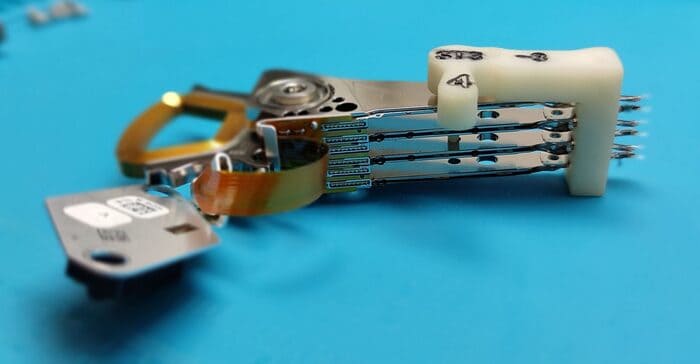
These are usually called voice coils, because they work on the same principle that loudspeakers and microphones use to move their cones.
The current creates a magnetic field around the coil, which pushes against the field of the permanent bar magnets.
Remember that the data tracks are tiny, so the arms must be positioned with extreme precision, just like everything else in the drive.
Some drives have dual-stage actuators, which make fine adjustments by moving only part of the arm.
In some drives, the data tracks partly overlap. This technology is called shingled magnetic recording (SMR), and it demands even greater accuracy and repeatability (hitting exactly the right position every time).
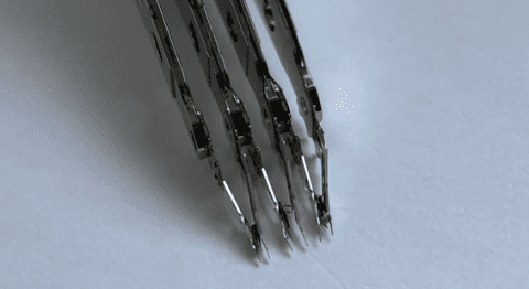
At the tips of the arms are the delicate read/write heads.
Our drive has 3 platters and 6 heads, and each head flies just above its platter as it spins. To make this possible, the heads are mounted on two ultra-thin metal strips.
This is where we can see why our sample drive no longer works: at least one head has come off, and whatever caused the original damage also bent some of the suspension arms.
The head assembly is so small that it’s very hard to get a good photo of it with an ordinary camera, as you can see below:
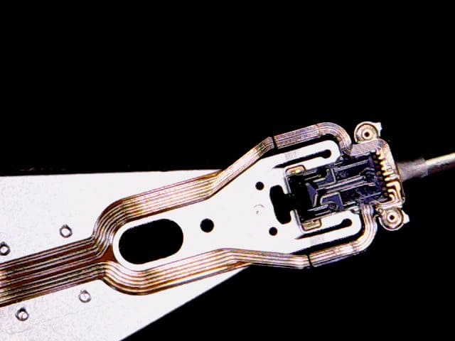
Even so, we can make out a few parts: the gray block is a precisely machined part called a slider. As the platter spins underneath it, the airflow creates lift that raises the head off the surface.
And when we say “off”, we mean a gap of just 0.0000002 inches, or less than 5 nm.
Any higher and the heads wouldn’t be able to detect the changes in the magnetic fields of the tracks.
If the heads actually touched the surface, they would simply scrape off the coating. That’s why the air inside the drive has to be filtered: dust and moisture on the platter surface would destroy the heads.
The tiny metal “pole” at the end of the head helps with its overall aerodynamics. But we need a better image to see the parts that actually read and write.
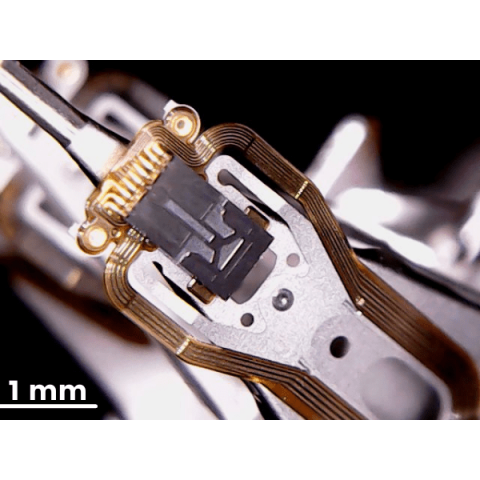
In the image above, taken from a different drive, the read and write elements sit underneath all the electrical traces.
Writing is done by a thin-film inductive (TFI) element, while reading is done by a tunneling magnetoresistive (TMR) sensor.
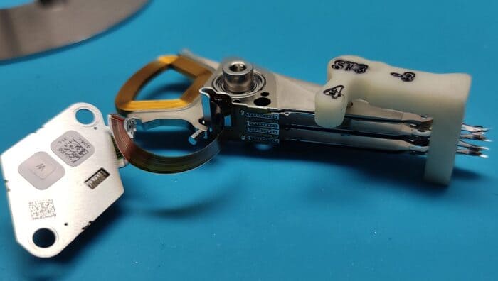
The signals produced by the TMR sensor are very weak, so they pass through a preamplifier to boost them before being sent to the circuit board.
The chip that does this can be seen near the base of the actuator arms in the image below.
Performance
We used CrystalDiskMark to benchmark a WD 3.5″ 5,400 RPM 2 TB hard drive:

The first two lines show the transfer rate in MB per second for sequential reads and writes (one long, continuous block of data) and random reads and writes (jumping around the drive).
The next line shows the IOPS value, the number of input/output operations completed per second.
The last line shows the average latency (in microseconds) between issuing a read or write request and the data being returned.
In general, the values in the first three lines should be as high as possible, and the value in the last line as low as possible.
Read next
Conclusion
As we said at the start of this article, the mechanical components and the way a hard drive works haven’t changed much over the years.
What has improved most is the technology behind the magnetic tracks and the read/write heads, producing narrower, denser tracks and therefore greater storage capacity.
However, mechanical hard drives have clear performance limits: the actuator arms take time to move into position, and if the data is spread across different tracks on separate platters, the drive spends several milliseconds hunting for the bits.
And remember: whether your drive has physical or logical damage, our team at Bot gives you the best chance of recovering your data safely, backed by more than two decades of experience.
Count on us if you need to recover your data. Start your recovery with us and become one of our more than 200,000 cases!


